In the automotive and aerospace manufacturing industry, CQI-9 and AMS2750 specifications are established as guidelines to:
“address pyrometric requirements for thermal processing equipment used for heat treatment. The document covers temperature sensors, instrumentation, thermal processing equipment, system accuracy tests, and temperature uniformity surveys. These are necessary to ensure that parts or raw materials are heat treated in accordance with the applicable specification(s).”
A critical part of the standards is the requirement to perform temperature uniformity surveys (TUSs). The TUS is performed to validate the temperature uniformity characteristics of the qualified work zones and operating temperature ranges of furnaces or ovens used. Ultimately, the TUS validates the temperature characteristics of the work zone and should closely match a typical heat-treat cycle with respect to ramp up speed and temperature.
To perform these surveys, heat treaters may use field instruments such as multi-channel chart recorders external to the furnace, or multi-channel chart recorders that ride in a basket on a continuous belt-type furnace (or oven). There are financial and physical considerations with both options. For example, the “thru-type” instruments have limitations regarding size of access (ingress and egress), duration, and temperature during the test process.
Furnace classification
One of the key considerations of a TUS is verifying the classification of the furnace and its qualified working zone. This determines the required ongoing testing schedule necessary to maintain conformity. The “qualified working zone” is the area of the furnace that will be used for the heat-treat process, and a TUS helps determine how close the working zone is to registering the desired temperature. The temperature uniformity range is described as a ± degree value, as shown in Figure 1.
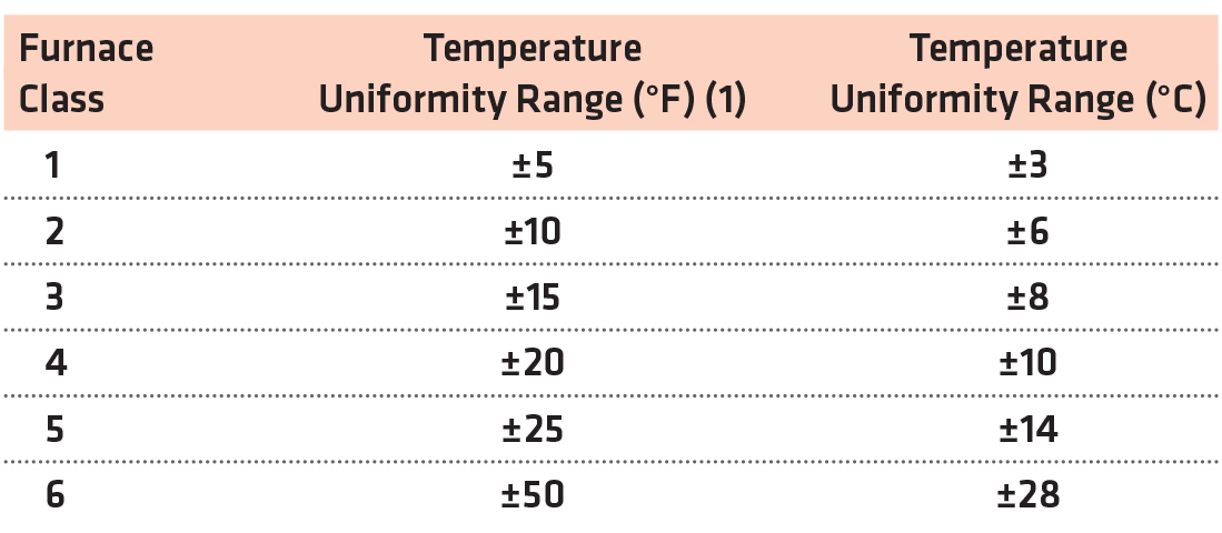
For example: A furnace is meant to run at 1,900°F and its qualified working zone ranges between 1,887°F and 1,913°F. This is a ± range of 13 degrees, so it would qualify as Class 3. A higher-rated furnace classification (class 1 being the highest) means that the furnace is able to stay closer to its target temperature without variation.
Survey frequency
Based on the furnace classification (and instrumentation type used to conduct the TUS), the guidelines clearly determine the testing schedule necessary in order to maintain certification (see Figure 2).

For example: A Class 2 furnace with instrumentation type B is required to undergo a TUS on a monthly basis, whereas a Class 5 furnace with instrumentation type B only requires a quarterly TUS.
However, AMS 2750 rewards success. If a furnace completes a designated number of TUSs successfully, the interval between testing can be increased. In the above example, if the Class 2 furnace were to submit to four consecutive successful TUS surveys, the required testing frequency adjusts from monthly to quarterly.
And of course, performing fewer TUS surveys has many benefits, including decreased time spent on surveying, less documentation of the process, lower cost of labor/materials, and increased production/reduced downtime.
Thermocouple measuring position
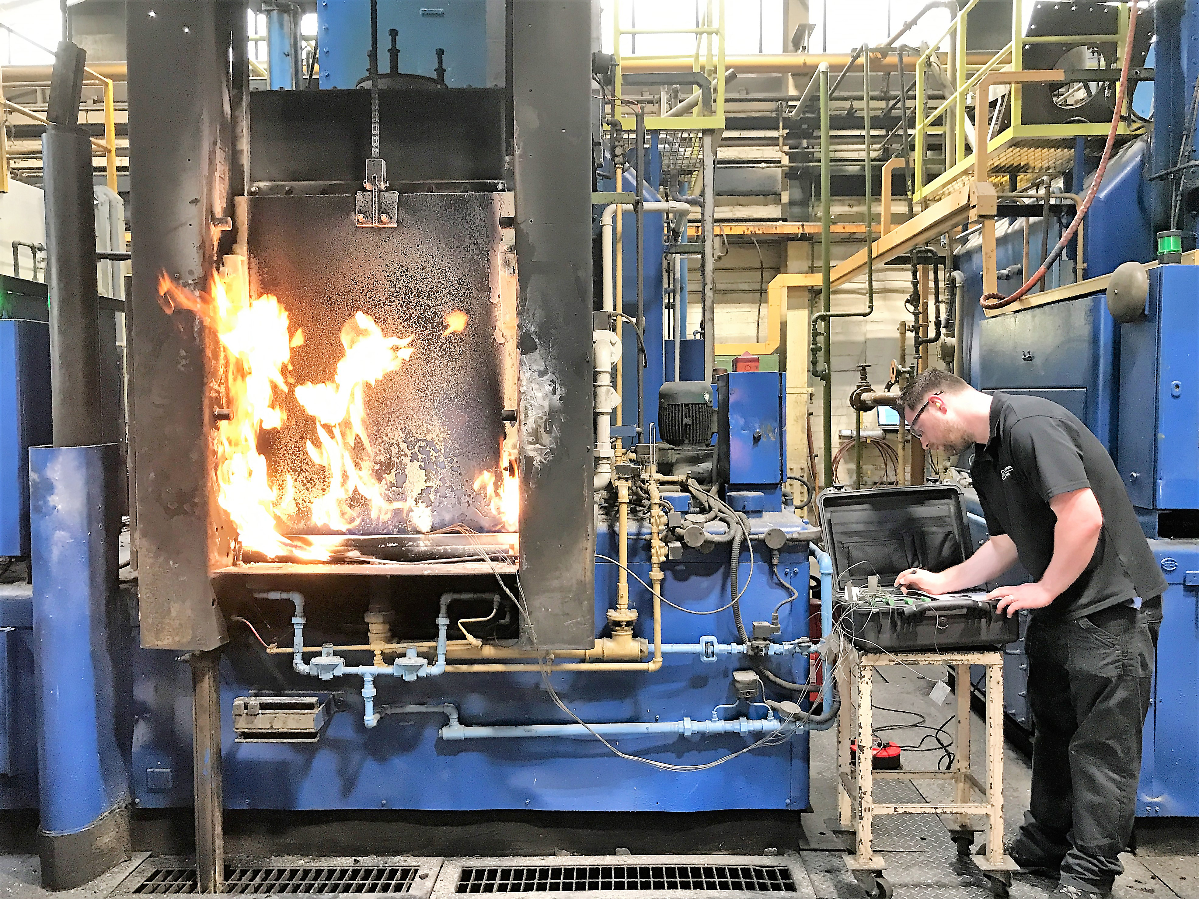
To perform the TUS survey, a TUS frame (or rack) must be constructed to locate the thermocouples over the standard work zone to match the form of the furnace (Figure 3). The TUS may be performed in an empty furnace (in which case thermocouples should be securely fixed to the rack or basket), or a furnace with a production load. Either method is acceptable, but once a procedure is established, subsequent surveys must be performed the same way on that equipment.
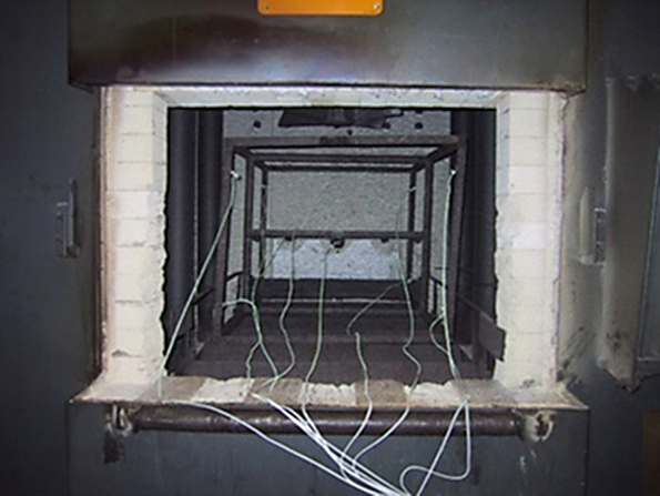
Note that a “typical” load weight and size is unpredictable for a commercial heat-treat operation, whereas a captive heat-treat operation may want to survey a furnace or oven with a specific part that it will run again and again. Due to safety practicalities, atmosphere is not required when performing a survey.
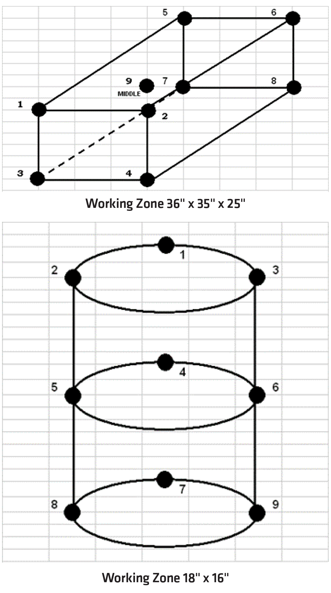
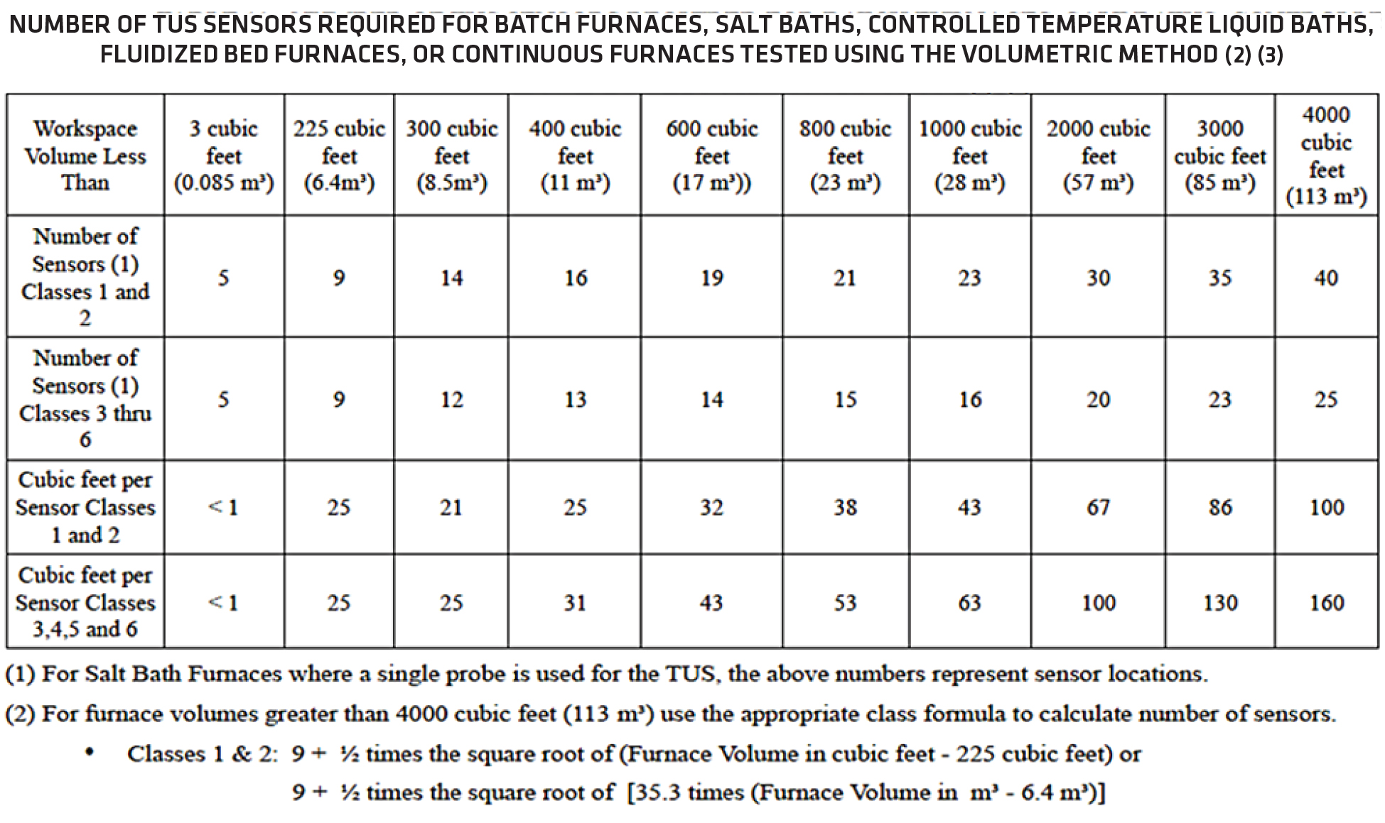
As required, the rack needs to be constructed to locate the thermocouples over the standard work zone to match the form of the furnace (Figures 4 and 5). The number of survey T/Cs are established by the workspace volume as indicated in Figure 6.
Tips for installing thermocouples
- Ensure the insulation on the thermocouples is not damaged and avoid contact of the wires with bare metal.
- For consistency, the tip or junction of the thermocouples should be welded and not twisted together.
- When possible, avoid running thermocouples through the door, causing leakage points in the load chamber.
- Try to keep the entry point where the thermocouples enter the oven constant. Shifts in the hot-to-cold transition points along the wire length can cause errors in readings.
- Keep the tips of the thermocouple at least three inches away from any surface.
- Avoid any sharp bends in the thermocouple — mechanical stress can cause an error in the calibration.
Tips for a TUS
Establishing proper procedures and training will improve your efficiency for executing a survey with accurate results. Some common tips performing a TUS include:
- Verify the proper furnace classification is assigned to each asset. Remember that a furnace can be classified in more than one way. However, a furnace cannot be used for a process for which it has not met the required temperature uniformity.
- Conduct the required number of survey-time data points, which specify two-minute intervals for each thermocouple. The data points must also include ramp (approach) and soak time.
- Make sure the recorder or any other electrical instrument used in conducting the survey is properly grounded.
- Be aware of any high-energy/high-frequency electrical equipment in the proximity of the survey (welding equipment, plasma cutters, EDM machines, etc.) as these types of equipment can be the source of EMF noise that may cause interference with the survey reading.
- Instrumentation (TUS device) calibration is mandatory, and the certification must state the calibration is met. The calibration documentation must state correction factors and identify the procedure for inputting these values into the report.
- Survey equipment must meet specific accuracy requirements, and the TUS device must comply to a calibration accuracy of ±1°F or ±0.1 percent reading in F.
- Thermocouple wire includes traceability certification. Calibration records must state the correction or error factor.
- Attention is to be paid to the selection and placement of the thermocouple on the survey rack. Assure the contact between the T/Cs and the rack.
- Clearly define the work zone in the survey. Parts not processed within the defined work zone are considered to be run in a non-conforming piece of equipment. If the work zone is larger than the rack, this will result in a major non-compliance citing.
- Establish and document TUS procedures for in-house survey technicians and third-party survey companies.
- It is not necessary to qualify a furnace for uniformity that is not required.

Reports
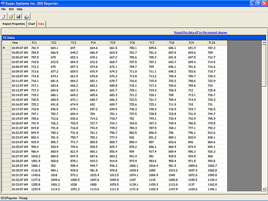
The reporting process should be consistent, easy to access, and provide the proper data points. AMS-2750E, 3.5.21.1 (below) mandates the items to be included in the survey report. AMS-2750 also provides a list of items that are not a required part of the uniformity survey report, but shall be accessible on site.
3.5.21.1 The following items shall be included in the temperature uniformity survey report:
a. Furnace identification name or number.
b. Survey temperatures.
c. TUS sensor and location identification including a detailed diagram, description or photograph(s) of any load or rack used.
d. Time and temperature data from all recorded sensors required for furnace instrumentation type for all zones tested (3.5.13.3.2).
Correction factors as well as corrected or uncorrected readings of all TUS sensors at each survey temperature. Readings shall be identified as corrected or uncorrected. (AMS 2750D)
e. Correction factors for TUS sensors at each survey temperature.
f. As found and as left TUS offsets (if used in production).
g. Corrected or uncorrected readings of all TUS sensors at each survey temperature. Readings shall be identified as corrected or uncorrected.
h. Testing company identification (if not performed in-house).
i. Signature for the testing company (if not performed in-house).
j. Identification of technician performing survey.
k. Survey start date and time.
l. Survey end date and time.
m. Survey test instrument identification number.
n. Indication of test pass or test fail.
o. When required, documentation of furnace survey sensor failures (See 3.5.16).
p. Summary of corrected plus and minus TUS readings at each test temperature after stabilization.
q. Quality Organization approval.
3.5.21.2 Although not a required part of the uniformity survey report, the following shall be accessible on site:
a. Control instrument tuning parameters.
b. TUS sensor calibration report.
c. Control and recording sensor calibration report.
d. Diagrams of control and recording sensors, load and TUS sensor locations in three-dimensional space.
Conclusion
Temperature uniformity surveys (TUS) are essential to a well performing heat-treat operation. Whether to conform to AMS2750E CQI-9, the goal is to ensure the heat-treating process is conducted to the tightest tolerances. Today’s heat treaters must find ways to better organize the testing process for ease of surveying and improved accuracy. Because there are many requirements to performing the TUS, time, organization, planning, and coordination are required to successfully administer the survey. To minimize the production downtime, build best practices for the activities that surround the TUS.
Understanding the TUS process will allow a heat-treat operation to be proactive regarding specific requirements and responsibilities and ultimately to be consistent and perform with reliable results. Once familiar with the equipment and the specification, a heat treater can prepare for efficient transition for surveying, minimize downtime, and streamline the process of TUS testing. And, investing time up front to document the process for future surveys, one can save time and money by identifying problems before they are too late to prevent. Be prepared:
a: organize paperwork.
b: ensure quick and easy access to maintenance logs.
c: fabricate and wire TUS racks in advance.
d: properly communicate equipment calibration dates.
e: develop reporting techniques for efficient review and signoff.
Best practices with proper planning and preparation can shave hours off the survey process. When multiplied by a large number of furnaces, the financial benefits become clear.


